

Inverters are a type of static converter, which includes many of today’s devices capable of “converting” electrical parameters in input, such as voltage and frequency, to produce an output compatible with the load’s requirements.
In general, renewable energy inverters, are devices that can convert direct current to alternating current and are widely used in industrial automation and electric drives. Even though the core of their main purpose is the same, the architecture and design of various inverter types differ depending on the application (DC to AC conversion).
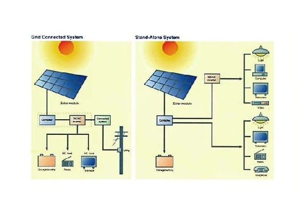
Standalone and Grid-Connected Inverters
Inverters used in photovoltaic applications have historically been classified into two types:
- Grid-connected inverters
- Standalone inverters
Grid-connected inverters can synchronize with the electrical grid to which they are connected because the main grid “imposes” voltage and frequency. These inverters must be capable of disconnecting if the main grid fails in order to avoid any potential reverse supply of the main grid, which could pose a serious risk.
Standalone inverters, on the other hand, are used when the PV plant is not linked to the main energy distribution network. The inverter can supply electrical energy to the connected loads while maintaining the main electrical parameters stable (voltage and frequency).
This keeps them within predefined boundaries, allowing them to withstand temporary overloading situations. In this case, the inverter is linked to a battery storage system to ensure a consistent supply of energy.
The distinction between standalone and grid-connected inverters is no longer as clear because many inverters are designed to operate in both standalone and grid-connected modes.
In fact, some distribution system operators (DSO) permit or even require specific generators to remain operational in the event of a grid failure in order to supply energy to a specific area or load. This is known as “island operation mode,” and it corresponds to the conditions described for the standalone application.
PV Inverter Architecture
Manufacturers make a variety of design decisions that result in significant differences between inverter models. Knowing this, we will present the key features and components found in all PV inverters.
Figure 2 – The general architecture of a three-phase solar inverter.
The inverter’s input section is represented by the DC side, which connects the PV plant’s strings. The number of input channels is determined by the inverter model and power, but it has no effect on inverter operation.
Assume for the time being that all of the strings are coupled before the inverter with a pre-parallel box, and that the inverter has only two inputs: + and -.
MPPT Converter
The maximum power point tracking (MPPT) converter is the first thing to notice after the input side of the solar inverter. MPPT converters are DC/DC converters designed to maximize the power produced by the PV generator.
It should be noted that this specified device converts the characteristics of the electrical parameters at the input into the desired ones (typically, it increases or decreases the input voltage), while always operating in direct current mode. In fact, the power of the PV module is heavily dependent on the climatic conditions of the site (mainly irradiance and temperature).
Each PV module (or string) can be characterized by an I-V curve (shown in Figure 3), from which the maximum power conditions can be calculated (Imp, Vmp). As a general rule, this curve is available in each PV module’s datasheet and is calculated using the Standard Test Condition, STC: (1000 W/m2, 25 °C, IAM 1.5). To learn more about IAM, read How Radiation and Energy Distribution Work in Solar PV.
Figure 3 – Example of I-V curve of a PV module.
Voltage and current change when temperature and irradiance differ from the STC, resulting in I-V curves that differ from the STC. Figures 4 and 5 show how the I-V varies with temperature and light intensity. Obviously, the maximum power point will change as well, so the MPPT algorithm will always seek this point to maximize power output.
Figure 4: Temperature-dependent I-V curve.
Figure 5 – I-V curve and Power curve at different irradiations.
The Perturb and Observe Method
The “perturb and observe” method is the most commonly used method for achieving the MPPT algorithm’s continuous hunting for the maximum power point. Essentially, the algorithm perturbs the working conditions by changing the voltage at a predetermined frequency and then checks to see if the new operating point actually corresponds to a higher power.
If this is the case, it will continue in the same manner by changing the voltage. If it is an increase, it will continue to try to increase. Otherwise, it reverts to the previous operating state. It is continuous and very fast tracking, with very small voltage changes (less than 1V).
Inverter Conversion Bridge
The conversion bridge itself serves as the inverter’s “core.”
Figure 2 depicts a three-phase inverter, with two switching devices, commonly MOSFET or IGBT, connected to each “leg” of the bridge — nowadays, three IGBTs are the most common solution for solar inverters. The IGBT’s switching behavior is governed by control logic in order to produce DC to AC conversion. Pulse width modulation is the most common switching strategy used to generate a sinusoidal waveform from a DC signal (PWM).
The Inverter Filter
The inverter’s final section is the filter section, which is designed to compensate for the harmonic content produced by all previous sections and clean up the output waveform.
The main source of harmonics is the switching of the IGBT. It introduces waveforms with frequencies higher than the fundamental.
How to Choose the Proper Solar Inverter for a PV Plant
When connecting a solar inverter to a PV plant, it’s critical to ensure that a few parameters match.
Once the photovoltaic string is designed, the maximum open-circuit voltage (Voc,MAX) on the DC side can be calculated (according to the IEC standard). As a result, the first critical check is to ensure that the maximum open-circuit voltage that the inverter can tolerate is greater than that produced by the PV field:
V OC, MAXINV V OC, MAXPV
The short circuit current match is the second critical check. It is critical to ensure that the PV field’s maximum short circuit current is less than the maximum current allowed by the inverter. This rule applies to all inverter inputs.
ISC, MAXPV, IDC, and MAXINV
The final two critical checks are related to the MPPT algorithm. This algorithm operates within a specific voltage range. To maximize yield, ensure that the maximum and minimum PV voltages at MPP conditions (as determined by the site’s climatic conditions) remain within the MPPT voltage range.
If this does not occur, the inverter will continue to operate, but the plant will not produce as efficiently.
V MPP, MAXP V V MPPT, MAXINV
V MPP, MIN PV V MPPT, MININV
Checking Inverter Efficiency
Finally, it is critical to examine the inverter’s overall efficiency. Nowadays, the efficiency of renewable energy inverters on the market is very high, with some manufacturers declaring values as high as 99 percent, while more common values range from 97 to 98 percent. Defining efficiency as a single peak value, on the other hand, is not entirely correct. True efficiency is affected by load and temperature.
As a result, the following three characteristics are frequently found in the datasheet of an inverter:
- Euro efficiency
- CEC efficiency (California Energy Commission)
- Peak efficiency
Euro and CEC efficiency take into account the inverter’s different load conditions based on specific site conditions — the continental European climate (for Euro efficiency) and the climate in the southwest US regions (for CEC efficiency) (for the CEC efficiency). So, basically, both approaches weigh the inverter’s efficiency at specific load conditions based on the times the inverter will work at that condition in that specific site.
Peak efficiency is the efficiency at maximum inverter power and is usually the nominal value in the datasheet.
Excellent resources are available to help you better understand the Euro and CEC efficiency formulas. These standard methods for calculating overall inverter efficiency yield a far more realistic value than the stated peak efficiency.